Turbomachinery: Laser Welding for Turbomachinery Rotor Restoration: Part two
11 April 2023
Written by Michael W. Kuper, PhD., Materials Engineer, Elliott Group and Michael J. Metzmaier, Welding Engineer IV, Materials Engineering, Elliott Group
Laser Beam Welding for Rotor Restoration
Powder vs Wire Filler Metal Delivery
For shaft repairs, LBW-W is generally more applicable than LBW-P. The first reason for this is that LBW-W has a lower probability of forming defects, namely porosity, which may result in rejectable surface indications after final machining.
Second, the ability to use a pulsed laser source in LBW-W reduces heat input, which helps minimize distortion, residual stress, and the size of the HAZ [8].
Third, wire filler metal is cheaper and more readily available than powder in general, and it may be the only option available for the carbon and low alloy steels commonly used as turbomachinery shaft materials.
The Post Weld Heat Treatment
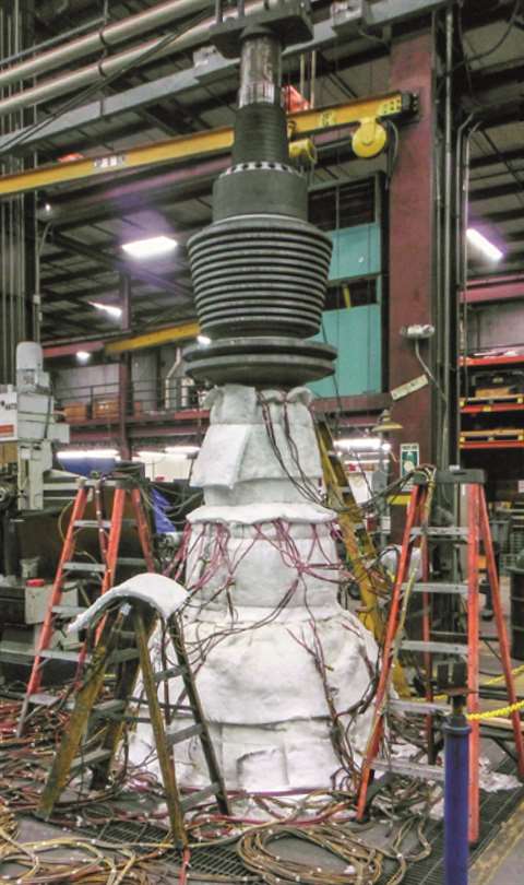 Figure 4. Post Weld Heat Treatment Setup
For rotor repair using conventional arc welding, a PWHT is generally required. First, residual stress from arc welding is large enough to cause shaft movement after final machining, particularly during the heat stability test that is required for turbine rotors.
The PWHT relieves residual stress to minimize shaft movement during machining. Also, because rotors are typically quenched and tempered martensitic steels, welding creates hard and brittle untempered martensite in the weld deposit and HAZ.
Untempered martensite reduces impact toughness, potentially below the base material requirements, especially for low-temperature service.
The PWHT tempers the fresh martensite that formed during welding, which restores the impact toughness of the shaft. Unfortunately, the PWHT can also over-temper the base material, which may result in a loss of strength in some cases.
Post weld heat treatment is also a costly and time-consuming operation. Figure 4 shows the setup for a PWHT applied to a rotor.
For this process, the shaft must be suspended vertically to minimize distortion. In other words, if the rotor were heat treated horizontally, the rotor would bow and sag between supports that would become permanent after the heat treatment.
After suspending the shaft vertically, heating blankets and thermocouples are added which must provide intense, yet precise heat (generally over 1000 °F), and this heat must be evenly distributed.
If heat is added non-uniformly, then stress will be relieved non-uniformly, which could result in detrimental distortion.
Heating/cooling rates and hold times must be controlled and monitored carefully. Overall, the process is relatively complex, time-consuming, and costly.
Often, laser weld applicators make the assertion that a PWHT is not required with their process because the weld deposit and HAZ created by laser welding are small enough that their presence has a negligible effect on the overall shaft properties.
However, little academic research has been performed on mechanical properties of laser weld repairs in turbomachinery applications.
While the weld deposit and HAZ may be small, it is dangerous to assume that they will not affect the shaft’s fitness for service, particularly when the shaft material is quenched and tempered steel, which is the most commonly used shaft material.
In order to avoid the PWHT, precautions must be made to ensure that the repair will meet the required properties without the PWHT. These precautions include the testing recommended later in this article, as well as considering compatibility with the erosion and corrosion requirements of the operating environment.
Current Qualification Requirements
As mentioned above, current ASME BPVC does not distinguish between LBW-P and LBW-W, nor does it account for the inevitable change over time in output power for Nd:YAG lasers.
This will need to be remedied in the future to account for the differences in the typical applications for and qualification of these processes. Regarding procedure qualification, groove welds would be qualified to ASME BPVC Section IX Table QW-451.1.
However, for rotor restoration, LBW repairs are typically performed on superficial damage, and would therefore be considered weld overlays. The procedure qualification requirements for overlays from ASME BPVC Section IX Table QW-453 can be found in Table 1 below along with the requirements for groove welds.
 Table 1: Procedure qualification test requirements for overlays and groove welding per ASME BPVC Section IX.
Although hardness readings are required for hard facing overlays, ASME does not list acceptance criteria.
Therefore, hardness limits should be applied based on the application and service environment conditions on a case-by-case basis.
As mentioned before, most rotor repairs qualify as weld overlays, but in addition to the above requirements, further testing may be necessary for laser beam welding in some instances.
In general, the critical design factors for shafts should also be considered, which are dependent on which portion of the shaft requires repair.
Critical Properties Based on Weld Repair Location
The most common locations for damage on a shaft undergoing restoration include the coupling fits, journals, probe areas, seal areas, and the main body.
Because of the nature of the repair process (fusion of the weld deposit and the formation of the HAZ), it is understood that the properties of the repaired areas will not match the properties of the original shaft material.
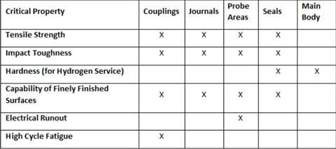 Table 2: Critical material properties based on the repair location.
Additionally, each part of a shaft has its own set of design criteria. Therefore, it is important to ensure that the restored areas meet the minimum design requirements at each repair location.
With that in mind, below is a discussion of the critical properties that should be considered for each region of the shaft. A summary of this information is found in Table 2.
Shaft Main Body
Main shaft body repairs are usually located in the lowest stress areas, where matching the shaft material composition and properties is generally unnecessary. In these locations, the intent of the repair is to restore dimensions without creating distortion elsewhere.
Because the main body of the shaft is in contact with the process gas, weld repairs made on equipment used for hydrogen service (over 100 psig partial pressure of hydrogen) must be constrained to a maximum yield strength of 120 ksi and a hardness of 34 Rockwell C to meet the requirements of API 617.
Accordingly, further analysis is required to determine if and how LBW may be applied for rotor repair that will operate in hydrogen service.
Journals, Seals, and Probe Areas
Journals, seals, and probe areas are generally smaller in diameter compared to the main body of the shaft, so stresses in these locations are moderately high and should be accounted for when selecting a repair method.
Tensile strength and toughness should be part of repair evaluation in these areas. Journal areas must also be capable of meeting surface roughness requirements after final machining and grinding (typically 32 micro-inch or better), meaning porosity could be a concern in these locations.
Repairs located in probe areas must have uniform microstructures to prevent erratic electrical runout readings. Probe areas are typically ground and burnished to maximize probe precision and accuracy.
The filler material must also act as a target material for the eddy-current probe and changes to probe calibration may need to be considered.
Although hardness is not a major concern for journals and probe areas, seal areas will be in contact with the process gas and must meet the maximum strength and hardness requirements mentioned above if the rotor operates in hydrogen service.
Couplings
The coupling area is usually one of the smallest diameters on the entire shaft, which means it experiences some of the highest stresses. This area may also contain additional stress concentrators such as keyways, grooves, or compression fits.
Unless there are other highly stressed integral features on the rotor such as turbine disks, the strength of the entire shaft is selected based on this feature.
This portion of the shaft may also experience high alternating stresses, which can be induced by the equipment that drives the rotor, meaning the endurance limit must be considered.
Care should be taken when determining the endurance limit since surface treated material may exhibit reduced endurance limits up to 50% as compared to the base material.
Therefore, direct testing of the fatigue characteristics is necessary in addition to tensile properties. Fatigue considerations of coupling repair is complex and requires additional considerations and testing that go well beyond ASME BPVC guidelines.
Because of the criticality and complexity of coupling repair design and assessment, repairs in this area are not be considered in this article.
Based on the critical properties identified in this section, the testing required by ASME BPVC Section IX alone is inadequate to assess the suitability of the repair for all common repair locations, except for the main body of the shaft.
To remedy this discrepancy, it is recommended to perform supplemental tensile testing and impact testing, at a minimum, for all repair qualifications made in the journal, probe, and seal areas.
Hardness measurements must also be taken for main body and seal repairs in cases where hydrogen service limits the rotor yield strength. In addition, coupling areas require additional considerations related to fatigue testing that are outside the scope of this article.
Laser Welding Procedure Qualification – Mechanical Testing
The following section details example test results from LBW performance qualifications on low alloy steels commonly used for shafts.
Each of these base metals were welded using AWS A5.28 Class ER120S-1. The materials used in this study, including the abbreviations used in this paper, the relevant industrial standards, and composition limits for primary alloying elements in each material can be found in Table 3.
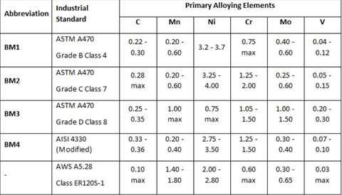 Table 3: The abbreviation, industrial standard, and composition of primary alloying elements for the materials described in this section.
All weldments were made using a 900 watt pulsed laser welding system with a fiber laser source. The welding parameters used for this study are considered intellectual property and cannot be shared in detail.
However, the same welding parameters were used throughout this study, with an average laser power of 522 W. This power is about 58% of the laser system’s capabilities, thus representing an intermediate deposition rate (approximately 0.10 lb/hr).
For each base material, a v-groove was machined into a 1 inch (25.4 mm) plate for welding.
The groove was machined with a 25° included angle (12.5° per side) to a depth of 0.625” (15.9 mm).
The depth was measured to the bottom of the groove, which was machined with a radius of 0.1875” (4.76 mm).
After welding, the weldment was liquid penetrant tested for surface defects, then test specimens were extracted for mechanical testing.
In addition to the groove weld, tensile specimens consisting entirely of weld metal were created by depositing and stacking layers of weld metal, each consisting of a pad of weld beads (similar to additive manufacturing).
The bars were approximately 0.5” wide, 0.5” tall, and 5” long. Two tensile specimens were extracted from each for testing. One test specimen was tested in the as-welded condition, while the other was tested after receiving a PWHT for three hours at 1200 °F.
The following list summarizes the mechanical tests performed for the LBW-W procedure qualification of each base metal welded in this study, with all specimens extracted from the v-groove weld except where noted.
- Two transverse tensile tests
- Six Charpy impact tests
- Three from the weld metal
- Three from the HAZ
- Hardness scan (Five indents each)
- Weld deposit
- HAZ
- Base metal
- Four side bend tests
- Two longitudinal tensile tests (extracted from the all-weld metal buildup
- One in the as-welded condition
- One after the PWHT)
Results
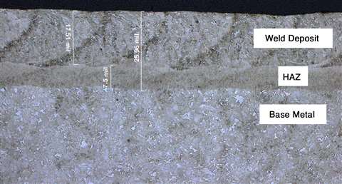 Figure 5. Cross Section of an LBW Overlay
All welds passed liquid penetrant testing and side bend testing. The macro test also passed inspection, meaning it contained no visible cracks at 5X magnification.
Figure 5 shows a cross section of an LBW overlay, which highlights the small size of the HAZ in the LBW overlay, averaging 0.00975” thick in this study. Additionally, the LBW weld deposit was clean with no detectable porosity. The dark speckles on the image are from slight surface rust.
Table 4 shows the results of the all-weld tensile tests including yield strength, tensile strength, elongation at failure, and reduction of area at
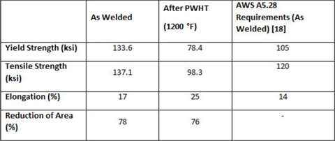 Table 4: Tensile test results from specimens extracted from all-weld metal (ER120S-1) buildups in the as-welded and PWHT condition.
failure.
This table lists the experimental values for the as welded and PWHT samples, and includes the property requirements of the filler wire from AWS A5.28.
The results from the groove weld tensile tests can be seen in Table 5 for each of the four base metals used. Test results include yield strength, tensile strength, elongation at failure, reduction of area, and the failure location.
The table also includes the mechanical property requirements from the base metal standards.
The results from the Charpy v-notch impact testing can be seen in Table 6.
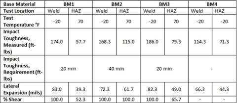 Table 6: Average impact test results for v-groove welds made with ER120S-1 on various base materials and the impact toughness requirements for each base material [19].
Test results include the test temperature, the average impact toughness, the average lateral expansion, and the average percent shear.
Also included are the mechanical property requirements from the base metal specifications, if applicable.
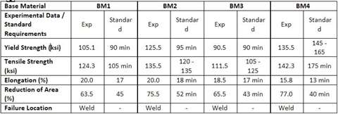 Table 5: Average tensile test results from v-groove welds made using ER120S-1 wire on various base materials and the mechanical property requirements for each base material.
The hardness survey results for each of the groove welds can be found in Table 7.
Table 7 also contains the measured thickness of the weld deposit and HAZ from each weld.
Example Repairs
In addition to the mechanical testing performed for the procedure qualification, repair welds were performed on two damaged shafts.
The first shaft was damaged by extensive pitting corrosion in the seal, probe, and journal areas, shown in Figure 6. The figure also shows the repaired shaft after welding and after final machining.
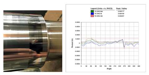 Figure 7. Example of a Burnished Probe Area after Repair (left). The repair region appears dark because of a difference between the base and weld metal; however, the repair met the geometric tolerances, surface finish, and electrical runout (right) required for a probe area.
The probe area was also ground and burnished, which can be seen in Figure 7 along with the electrical runout measurements.
The difference in color between the repaired area and the rest of the shaft resulted from the difference in hardness of the substrates during burnishing, however, the mechanical and electrical runout readings were within the required tolerances.
 Table 7: Average Vickers hardness (HV10) and thickness of the weld metal, HAZ, and base metal for each material welded with ER120S-1.
Figure 7. Example of a Burnished Probe Area after Repair (left). The repair region appears dark because of a difference between the base and weld metal; however, the repair met the geometric tolerances, surface finish, and electrical runout (right) required for a probe area.
The second shaft was damaged by a box cutter while being unpackaged for assembly, shown in Figure 8.
The scratch was approximately 0.003 inches deep and was repaired locally using a single weld bead, which can also be seen in Figure 8. After repair, the shaft was ground back to geometric specifications, inspected, and installed for service.
Figure 8. The scratch (circled) in a journal area (left); the same scratch after LBW repair (middle); and the repaired area after final machining (right).
Mechanical properties: Tensile properties and impact toughness
The as welded ER120S-1 used in this study exceeded the mechanical property requirements of the AWS wire standard by 26.7%, 14.2%, and 21.4% for the yield strength, tensile strength, and elongation, respectively, in the all-weld tensile specimens.
These excellent values are speculated to originate from grain refinement caused by the rapid solidification inherent to the laser welding process.
 Figure 8. The scratch (circled) in a journal area (left); the same scratch after LBW repair (middle); and the repaired area after final machining (right).
Regarding the weldments, samples tested from each v-groove indicated that the mechanical properties exceeded the requirements of the relevant base material in all cases except for BM4.
Therefore, BM1, BM2, and BM3 can be welded with ER120S-1 with the process used in this study without having to worry about meeting the base metal mechanical properties.
The reason that BM4 weldment did not meet the BM4 base metal requirements is that this base material overmatches the weld material. ER120S-1 has a minimum tensile strength of 120 ksi, while BM4 has a minimum tensile strength of 175 ksi.
Despite this, the weldment performed admirably, achieving a 142.3 ksi tensile strength when tested. The higher strength exhibited here, as compared to the other welds, was likely caused by base metal dilution.
Despite excellent mechanical properties in the as-welded condition, the test specimen that received a PWHT showed a decrease in tensile and yield strength by 41% and 28% respectively, to levels that would be unacceptable when compared with all base materials used in this study.
As a result, this filler wire should not be used in situations that require a PWHT, unless the anticipated drop in strength is acceptable from a design perspective.
In general, the impact toughness results were exceptional. The impact toughness of all welded joints (those that had impact toughness requirements) were well above the required values.
Additionally, lateral expansion and percent shear results were also exceptional. It is speculated that these excellent results were due to the fine grain size of the weld metal, which can be seen in Figure 5, though further characterization and testing is required to confirm.
Hardness
As mentioned previously, ASME code requires hardness scans for weld overlay qualification, but does not set acceptance criteria. For rotor restoration, the most applicable restriction that may be applied is the maximum hardness requirement (34 Rockwell C) set by API 617 for compressor shafts operating in hydrogen rich environments.
This requirement would be applicable for main body and seal repairs, since these regions of the shaft contact the process gas. According to Table 1 of ASTM E140, which governs hardness conversion, 34 Rockwell C equates to 336 on the Vickers scale.
When subject to a maximum of 336 HV, none of the base metals used in this study would be acceptable for hydrogen service after repair welding because the HAZ hardness exceeds the defined limit.
Also, the weld metal exceeds the 336 HV hardness limit in all cases except for the BM3 weldment, which was measured at 335 HV and should be considered on the extreme borderline of acceptability. It should also be mentioned that BM4 could not be used for hydrogen service in any case, since the base metal hardness was also too high.
Because of the high hardness of the HAZ and weld deposit, none of the materials used in this study would be acceptable for hydrogen service in the as-welded condition.
The hardness of these regions could be reduced using a PWHT, however as mentioned before, the weld metal used in this study loses considerable strength from a heat treatment, which may be unacceptable for shaft applications.
Other filler metals may be more appropriate if a PWHT is necessary, but this is outside the scope of the current work. Additionally, the extreme hardness of the HAZ may require a substantial PWHT to meet the requirements of API 617 for hydrogen service, which may over-temper the base metal of the shaft, which could lower the strength beyond the limits set by the application.
As a side note, it should be mentioned that a potential solution to this issue would be to perform a localized PWHT using induction heating, which has a skin effect that may be able to temper the HAZ without significantly over-tempering the bulk of the shaft.
This possibility has not yet been explored and warrants further study. Regardless, because of the reasons outlined here, LBW may not be the best option for repair in cases involving hydrogen service, particularly when the base material is quenched and tempered steel.
Finish
Since geometric runout was within the allowable limit (0.002”) after welding and finish machining, distortion induced by LBW was insignificant. No surface indications were found after final machining, meaning no porosity was detected during the liquid penetrant test.
Additionally, the probe area was successfully burnished using the standard process, resulting in acceptable geometric tolerances. The electrical runout test in the probe area was also acceptable within the tolerance limits, and in this case, the probe did not require recalibration.
It is hypothesized that the acceptable electrical runout can be attributed to the high degree of uniformity in the weld deposit, which resulted from the high degree of precision and control inherent to the mechanized LBW process.
Further study would be necessary to asses this hypothesis. For the scratch repair, there was some initial concern that the localized weld would not “clean up” after final machining.
In other words, it was predicted that cratering at the weld start or stop, or undercutting along the weld toes may lead to negative space (missing material) after final machining. However, final machining to the original dimensions after welding produced a smooth surface without topological defects or low spots.
Advantages of Laser Weld Repairs: Scratch Repair
The scratch which was approximately 0.003” in depth would have rendered the shaft as scrap without a viable repair process. Traditional arc weld was eliminated as an option due to the fact that it would have required welding from the journal area through the coupling end of the shaft.
Welding in the coupling area was not feasible in this case due to the strength requirements in that location. Instead, the laser welding process was utilized to perform a localized repair of the scratch, eliminating the need for welding in the coupling area while saving significant processing time.
Final grind of the repair area did not require additional stock removal beyond the original drawing tolerance.
Overlay Repair
The turbine rotor shown in Figure 6 sustained extensive pitting corrosion damage in the seal and journal locations. Conventional arc weld overlay of those areas would have required a multi-step process to repair.
First, all damage and protruding features (i.e., packing teeth, balance rings, thrust disk, etc.) would be machined off of the shaft with an additional undercut of 0.125” radial stock.
 Figure 6. Shaft Damaged by Extensive Pitting
The shaft would then be welded, building up material as required to restore the geometry of all features, with extra stock added for machining and to account for distortion from the welding process.
The weld repair would then require a stress relief heat treatment to remove residual stress. This is necessary because the residual stress would tend to move the shaft during machining, which would result in a high probability of failing to meet the required geometric tolerances.
In the case of turbine shafts, removal of residual stress is critical to passing the heat stability check. After stress relief, the shaft would be final machined and then undergo non-destructive testing. Turbine rotors would then be subject to the aforementioned heat stability check.
By using laser welding, the repair process would require fewer steps. First, the damaged areas would be undercut, though undamaged areas, including protruding features, may be left on the shaft.
Second, the LBW overlay would be performed to restore shaft dimensions with an additional 0.020” machining stock. Third, the repair would be machined to meet the drawing dimensions, and lastly, the prescribed non-destructive testing would be performed to check for defects.
Overall, this process requires significantly less machining before and after the weld repair, and it eliminates the PWHT. Also, in the case that the rotor is being clad with a corrosion resistant material such as nickel based alloys, LBW deposits less material, which may offer costs savings.
It should be noted that the time to overlay weld a shaft may be longer for LBW than a conventional arc welding processes, like submerged arc welding, but the faster machining times and elimination of the PWHT when using LBW generally make up for any time lost during welding by a considerable margin.
Of course, this depends on a variety of factors including the size of the rotor, the extent of repairs, the complexity of features, etc., so the best weld repair process for a given application can vary and should be selected on a case-by-case basis.
Nonetheless, LBW offers clear advantages in many cases for repair of superficial damage, which occurs commonly over time and exposure to service conditions.
Conclusions
Laser welding, when applied correctly, is an effective method for the restoration of turbomachinery shafts. The process is quick and efficient in performing superficial repairs, and in some cases allows for the repair without the need to perform a PWHT, which saves further time and costs.
However, in order to perform LBW repairs outside of the main body of the shaft, it is important to fully qualify the welding procedure with supplemental testing to ensure the integrity of the as-welded repair.
This testing includes tensile testing, impact testing, and hardness. While not discussed extensively in this paper, fatigue testing is also critical for coupling repairs.
Furthermore, these requirements and recognition of the differences between wire and powder based filler metal delivery in LBW need to be addressed by Section IX of ASME BPVC to ensure compliance to these practices as an industry standard.
Nomenclature
HAZ = Heat Affected Zone
LBW = Laser Beam Welding
LBW-P = Laser Beam Welding (powder filler metal)
LBW-W = Laser Beam Welding (wire filler metal)
PWHT = Post-Weld Heat Treatment
SAW = Submerged Arc Welding
WPS = Welding Procedure Specification
About the authors
Dr. Michael W. Kuper is a materials engineer in the Product and Technology Group at Elliott Group. He has a B.A., an M.S., and a Ph.D. in Materials Science and Engineering from the Ohio State University.
His past experiences include analysis of dissimilar metal welds involving 9Cr-1Mo-V steel welded with nickel based filler metals, and high deposition rate additive manufacturing of metallic materials.
He currently has 5 publications, has presented research at more than a dozen technical conferences, and is an active peer reviewer for the journal Welding In the World.
Michael Metzmaier is a welding engineer in the Materials Engineering Department at Elliott Group. He has a B.S. in Welding and Fabrication Engineering Technology from the Pennsylvania College of Technology.
He has held various positions within Elliott Group includling manufacturing engineer, rotor division supervisor, and welding engineer.
POWER SOURCING GUIDE
The trusted reference and buyer’s guide for 83 years
The original “desktop search engine,” guiding nearly 10,000 users in more than 90 countries it is the primary reference for specifications and details on all the components that go into engine systems.
Visit Now
STAY CONNECTED


Receive the information you need when you need it through our world-leading magazines, newsletters and daily briefings.
CONNECT WITH THE TEAM

